The Petri net is a bipartite digraph with places and transitions as nodes. Bipartite refers to the property of the mesh to have two disjoint subsets of nodes, namely the
•places or locations (represented by the circles) and
•transitions (represented by dashes or rectangles).
Digraph means a directed graph that always connects nodes of different types. You can connect any number of nodes of one type with any number of nodes of another type.
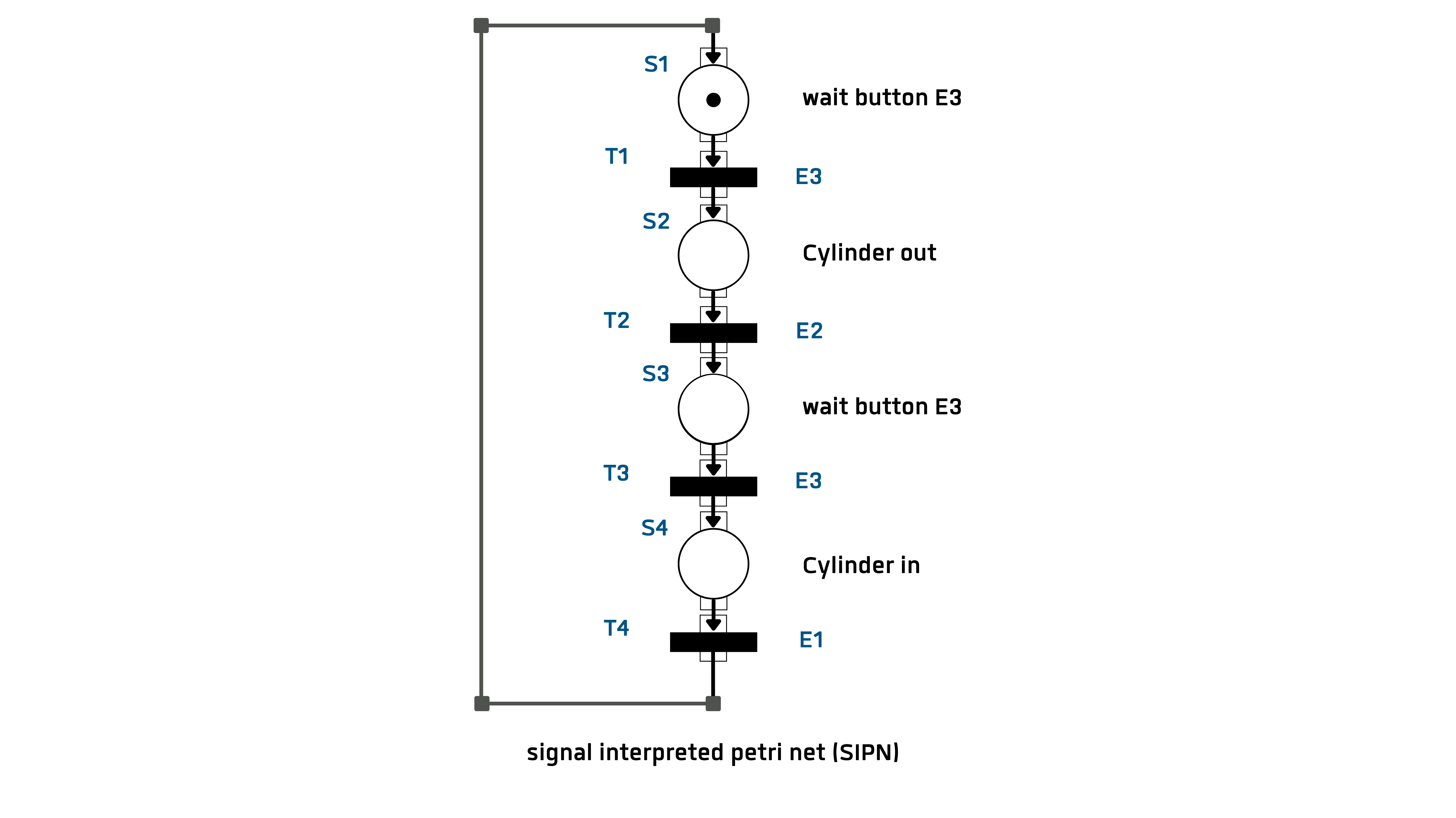
Squares and transitions are numbered or labeled with a text. A transition cannot contain a marker. In the graphic, place S1 is marked with the start marker. This marker jumps to the next position when the transition condition is fulfilled. Each transition is assigned a switching condition, which can be a Boolean function of all input signals. Once a marker has reached a position, the defined outputs are activated. A detailed description of the SIPN is not given here, but reference is made to the following literature. (Litz L. , 2005); (Lunze, 2003)
The input vector for the control example is
eT = [E1 E2 E3] = [ rear cylinder front cylinder key];
The output vector for the control example is:
aT = [A1 A2] = [Valve cyl._before Valve cyl_back]
The switching conditions of the transitions are:
SB(T1) = E3
SB(T2) = E2
SB(T3) = E3
SB(T4) = E1
The output variables at the points are:
aTS1 = {0 0}; aTS2 = {1 0}; aTS3 = {0 0}; aTS4 = {0 1};